People have asked me if there's any way of stopping the HPS ballast from damaging the plug in 24 hour timers that are generally used for setting the lights on photoperiod. When the ballast is plugged directly into the timer, after a couple of months the timer stops working - this is because when the timer switches the lights off it causes arcing across the contacts inside the timer (this is due to the back EMF - high voltage pulse - that happens whenever you switch off something like a transformer or a choke like is found in the HPS ballast) which eventually forms a layer of copper oxide over the contacts and stops them conducting. This can be prevented by the addition of a 'snubber' network between the timer and the ballast.
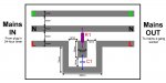
A snubber network absorbs the energy of the EMF pulse and thereby prevents the arcing from occurring (stopping the oxidation which would coat the contacts and stop them working). The actual snubber consists of a resistor and capacitor connected in series between the live and neutral wires, whick is best achieved by making a small extension which also contains a box housing the snubber. I've attached a jpeg with the layout of a copper board (for anyone who etches their own PCB's) showing the positioning of the resistoe and capacitor. If you aren't electrically minded, print the jpeg and the info given below and either ask an electronic minded friend or get it made at an electronics shop (it's very simple, so shouldn't cost much).
Once completed, the max load that can be operated through the timer with the snubber extension is about 2.5kW (that's 6x400W lights; 4x600W lights or 2x1000W lights). In the long run it'll save you a fortune in timers burning out (and the inconveinience of a timer burning out at a critical stage in the flowering process - from what my friend has told me, you can guarentee that's when it'll happen!)
Anyway, the info needed that isn't included in the jpeg is as follows
C1 - 100nF/0.1uF, 250V capacitor (X2 rated - means suitable for connecting across mains voltage)
R1 - 100 ohm, 1W metal film resistor.
Other than that you'll need a plug (with 13A fuse), a trailing socket (4 gang probably best for what you'll be using it for), a plastic box to hold the circuit board (it has to be plastic/ABS and not metal in order to insulate the board and prevent accidental touching/contact with board in operation) and about 2m of 13A, 3 core cable. It'll also be best if you have some sort of glue to seal the holes where the 13A cable enters & exits the box containing the circuit board.
If anyone has difficulties, just send me a pm and I'll sort it out. If enough people find this useful, I'll put some more stuff up for things like an intermittant pump controller - only pumps water for short bursts every couple of hours while lights are on (ideal for hydroponic type systems). Even could put up cct diag for building a complete lights/fans/water pump and system failure unit (the sort of thing that can be left for a week at a time to take care of all your plants needs)
Hope this proves useful